
History of The M7A1, M7A2, and M7A3 Grenade LaunchersThe Recoiling Grenade Launchers © |
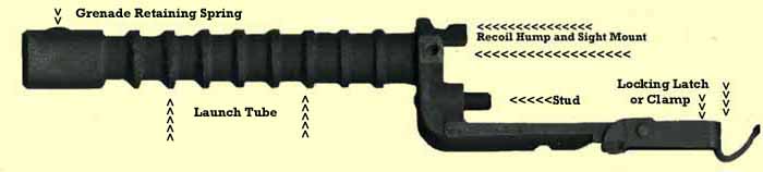
The M7A1, A2, and A3 Grenade Launchers (GL) are unique when compared to other GL's. Although each design is slightly different, they all are direct descendents of the T95. Unlike the others, these GL's move rearward and return to their original position to operate. This is the story about the research and development of this special group of GL's known as the "Recoiling Grenade Launchers".
Early 1945
As WWII was ending, Ordnance was working on giving the grenadier carrying an M1 Rifle semi-automatic capability and preventing the high loss of GL's. At that time the standard grenade launcher for the M1 Rifle was the M7. It had a long stud which kept the gas system opened. This allowed venting of the operating gases to prevent injury to the operator and damage to the rifle. It was accomplished by a valve inside the Gas Cylinder Lock Screw (lock screw). The long stud automatically depressed the valve to the opened position, which allowed gases to escape from the gas system. The disadvantage of such a system was its inability to fire semi-automatically. As long as the M7 remained on the rifle, the gas system remained opened. To re-gain semi-automatic capability the operator had to remove the launcher, which disabled it in its role as the rifle squad's grenadier. The constant removal and mounting of the M7 led to high losses. According to ordnance documents between 15% and 20% of M7's in inventory were being lost each month.
Click Here for the terms used in this history. Throughout this article you will find hyperlinks in blue. You must use the return button on your browser to return here. The hyperlinks will bring you to a website or to illustrations that are too large for this page.
The M7 Grenade Launcher was used throughout WWII with an early style vented lock screw. A close examination will reveal the valve remained open. Not until the launcher was removed would the gases from service ammunition close the valve, which would allow semi automatic fire. The screw was initially submitted by Remington Arms with its T14 Grenade Launcher. It was eventually adopted with the T14, which evolved into the M7. During the later part of the war the screw was upgrade to a "poppet" valve system which automatically closed once the launcher was removed.
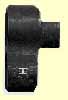
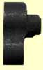
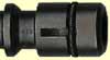
At right is a close up of the Gas Cylinder Lock Screw with the valve opened, venting the gas system. The launcher's stud enters the lock screw from the right and opens the valve. Illustrated is the valve's "head" which seals the gas system when closed.
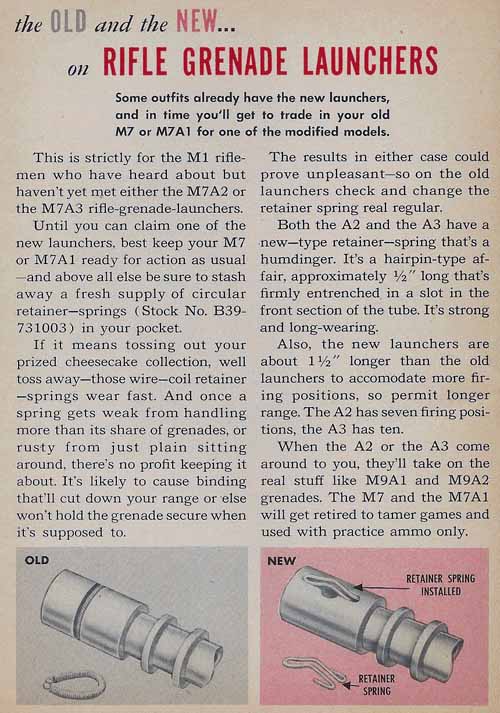
In early 1945 it was decided to develop a launcher that had the following characteristics.
- Launcher to allow semi automatic fire with service ammunition.
- Launcher to vent the gases only during grenade launching.
- Launcher must be capable of remaining on the rifle while complying with the above two functions.
A few different designs were tested. Some designs used the "Bottoming" principle to insure semi-automatic fire. With this method the gas system remained closed until a projectile was placed in the bottom position on the launcher. The bottoming of the projectile mechanically moved launcher components to open the gas system. The bottoming method was not new. In 1943, during the initial tests which led to the adoption of the M7 GL, several designs used this method. The requirement to bottom mount a projectile was found to be an undesirable feature. A projectile that was inadvertently not mounted at the bottom would not open the gas system, leading to accidents and malfunctions. This feature was considered too dangerous for adoption and all future designs were rejected.
Designs Competing For Adoption
Colt submitted the T84. It evolved into the T84E2, illustrated here. The T84 was eliminated due to the bottoming requirement. The T84E1 and E2 allowed manual closing of the valve by the operator, which attempted to eliminate the bottoming requirement. They were rejected for safety reasons. If the operator failed to manually open the valve, injury or damage could occur. Colt's launcher also required a special lock screw, and would not interchange with the standard "poppet" valve lock screw.
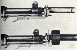
The T85 shown in this illustration used a sliding sleeve and a floating stud to open the valve. Manual rotation of the sleeve allowed the operator to move the stud in or out, opening or closing the gas system. For safety the launcher had a shield to block the front sight when the gas system was in position to fire a grenade, shown in the bottom part of this picture. This was used as confirmation to the operator that the system was opened. The design was dropped due to the manual requirements, carbon accumulation interfering with its operation, and a possibility of the inadvertent closing of the gas system when a projectile was mounted with a rotary motion.
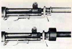
The T86 shown here relied on bottoming and worked with ball bearings. Its design was similar to the T85, but it used a sliding sleeve which was moved to the rear when a grenade was installed on the launch tube. The sleeve depressed a tube which opened the gas system. The tube was locked in position by three spring loaded ball bearings, which receded into a slot in the launcher's bracket. The launcher's components were fragile. The T86 was rejected.
All of the above designs were rejected due to a variety of reasons. The bottoming requirement would come back to haunt a future design in the early 1950's.
Springfield Armory's Answer Was The T95
The system that Springfield Armory used had a spring and plunger mechanism located where the launcher locks into the bayonet lug of the gas cylinder. The spring and plunger kept the launcher in a forward position, preventing the stud from contacting the valve inside the lock screw. During the firing of a heavy projectile the grenade cartridge's gases pushed the launcher to the rear like a piston. This rearward movement allowed the stud to open the valve in the lock screw, venting the gas system. This was accomplished two ways. The first was by compressing the spring and plunger assembly against the bayonet mounting lug on the gas cylinder. The second was with a slightly longer locking latch which allowed rearward movement of the launcher. After the projectile left the rifle, the plunger spring, which was under compression, rebounded to it original length, which returned the launcher to its forward position. This forward movement disconnected the contact between the stud and the lock screw's valve, which allowed the vent to automatically close, closing the gas system. This process occurred each time a projectile was launched, without having to rely on the operator. When using service ammunition the spring and plunger were strong enough to insure the gas system remained closed, allowing semi automatic fire with the launcher mounted on the rifle. This launcher was designated the T95, and would be standardized as the M7A1 in July of 1945. Although not technically correct, the easiest term to describe this type of design is the Recoiling Grenade Launcher system.
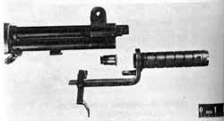
The prototype was an altered M7. The Springfield Armory T95 from mid 1945 was the first launcher to incorporate the recoil mechanism needed to maintain the semi-automatic capability with the launcher mounted on the rifle. This picture, taken from a history of Army Ordnance from 1946 shows the longer locking latch, recoil mechanism and a hardened insert. The T95's recoil mechanism, which consisted of a spring and plunger, was woefully inadequate and would be strengthened sometime after the prototype was standardized as the M7A1. The hardened insert was required to make up for the dimensional differences of this particular M7and the longer locking latch. The insert would be deleted from the production models because tube dimensions could be accommodated from the start, something that was not possible with some existing M7's.
The T95 System Affects the Design of The Gas Cylinder Lock
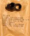
At the same time as the M7A1's standardization, Gas Cylinder Lock, Ordnance Part Number 7162247, was adopted for issue. Like its WWII predecessor, it was beveled in front. Unlike its WWII predecessor, it was hardened. This lock was marked with the letter "H". The hardening of the lock was an attempt to prevent it from becoming deformed when impacted by the GL.
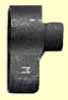
Illustrated at right are the two beveled locks that existed at the time of the M7A1's standardization. The bevels can bee seen at the top right of the locks.
The left one is the WWII lock, unhardened, ordnance part number 6147426. On the right is the lock from 1945, ordnance part number 7162247. This lock is known as the "hardened lock". The "H" marking is what distinguished it from the early softer lock.
Development of a Suitable Production Model Continues
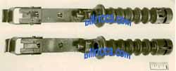
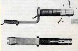
Rock Island Arsenal provided the production version designated as the M7A1. Here are two early designs which competed in the production model tests, at Rock Island. The T95 was an altered M7. Although it set the design standard, it was not practical to alter existing M7's. The M7A1 had a few different designs during its production trials. Both launchers shown here have a different stud, stud support, recoil plunger, and grenade retaining spring. A grenade retaining spring similar to that on the bottom launcher will be adopted at a later date. Photo courtesy of Springfield Armory, National Historic Site.
The M7A1 Production History 


Rock Island Arsenal, the only manufacturer, produced approx 21,000 M7A1's (1) during its fiscal year of 1949. The launcher was produced with two different part numbers, the most common being 7313290. There was also a very small quantity of launchers that were marked 7313286-3. The M7A1 consists of at least three components. The body, the locking latch and the grenade retaining spring are three separate parts which make up an assembled launcher. Each of these parts had its own ordnance part number. It is possible the 7313286-3 marking was the part number of the body, which was produced as a spare part. A second possibility is the 7313286-3 marked launchers were produced during an earlier production. Until somebody finds the ordnance drawing, the reason for the two markings will remain a mystery.
Shortly after fielding the M7A1, it gained the reputation for getting stuck on the rifle. To solve this problem, Lock, Ordnance Part Number 7265959 was designed. This lock was also hardened and was known as the "Flat Edge Lock". It is identified by the "M" marking. The flat edge was the cure for the launcher becoming stuck at an angle.
However, this was not the only problem with the M7A1. It would require the designing of an additional lock to make the launching of grenades more reliable.
Problems with the M7A1
After production of the M7A1's, problems from the field were reported. Although it solved the semi automatic problem, two other problems cropped up.
- The first and most serious was the sticking of the GL upon recoil. The M7A1 gained the reputation for becoming locked at an angle during it rearward travel. Even when used with the hardened gas cylinder lock, its bevel invited the launcher to over ride the top section and get stuck. The energy from impacting the beveled portion of the lock would make removal of the launcher almost impossible. At that point the rifle had to be taken out of service to be disassembled and repaired. Those repairs involved installing a new lock and lock screw.
- The second problem was caused by the velocity of the launcher during recoil. When used with the flat edge lock, heavier projectiles imparted such fast rearward movement that the launcher's stud would damage the valve inside the gas cylinder lock screw. Occasionally this caused the valve's head to break loose. The rifle would have to be dead lined until the gas system could be disassembled, the broken valve head removed from the inside of the gas cylinder, and a new lock screw installed. Not a job for the average GI in the field. APG was unsuccessful in addressing this problem with the T99E3.
T99E3 - Aberdeen Proving Grounds Design
The Aberdeen T99E3 never went beyond testing. Just a few were made. The design influenced the future test models of the M7A2. This launcher proved unacceptable in its attempt to limit rearward travel. There were several other experimental grenade launchers from the years immediately following WWII. This one recently surfaced and I had the opportunity to purchase it.
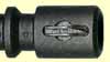
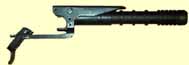
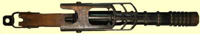
Aberdeen Proving Grounds (APG) Design T99E3 circa 1948. This was an early attempt to limit the rearward movement of the Grenade Launcher. The test used a specially modified M7 with the M7A1’s longer locking latch and a recoil limiting device (collar) surrounding the stud. Upon recoil, the collar impacted the lock screw and stopped rear movement. Not visible in picture is the recoil mechanism which consisted of the heavier spring and plunger located at the extreme right of the mounting bracket. This recoil mechanism, which was the same in the M7A1, M7A2, and M7A3, was a beefed up version of that used in the original T95 GL from 1945. This launcher did not utilize a hardened insert. The launch tube was removed, re-machined to different dimensions, and re-staked into the bracket. This prototype, a Hawley Smith Machine Company (HSMCO) M7 Grenade Launcher, was modified for testing by APG.
The solution was to re-design the M7A1 and have an additional gas cylinder lock which would limit the rearward movement of the launcher. Although it was sufficient to prevent the launcher from becoming locked from recoil, the Flat Edge Lock would not limit the rearward movement of the GL. Based upon the final production design of the M7A1, the M7A2 was engineered to be used with a newer gas cylinder lock.
The High Hump Lock, Ordnance Part Number 7265871, from 1951 was the answer. This lock was designed along with the M7A2 which was about to be put into production. Long considered the best option for launching grenades, this lock was included on rifles from that period. It was also included in most M7A3 Grenade Launcher contracts.
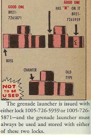
A 1952 issue of PS Magazine illustrated the newly adopted locks. The article used the term "Boss" in place of "High Hump". The other arrows emphasized the flat edge and the "M" marking.
The article treated both beveled locks (chamfered) the same, without distinguishing the WWII soft lock from the later hardened lock marked with an "H".
The lower part of this illustration is taken from a PS Magazine issue from 1960. It explained the required locks for use with the M7A2 and M7A3. By the mid 1950's the M7 and M7A1 were assigned to training areas only, but still required the same locks.
The M7A2 Grenade Launcher 

K. R. Wilson (KRW) of Arcade, New York, had the only contract to produce the M7A2, Ordnance Part No. 7265949. This launcher addressed the broken valve heads and was to be used with the newly developed "High Hump" lock.
The launcher was standardized in July of 1951 and KRW was issued a contract for 96,000. The first 13,000 launchers had the standard coil spring as a grenade retainer. Mostly all of those would be upgraded to accept the improved spring which also was a newly developed item. Not many M7A2's got into production because by September of 1952 the M7A3 was on its way. KRW's final contract was changed to the production of the M7A3(2). KRW had little to change over when making the M7A3, which was based upon the M7A2 design.
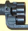
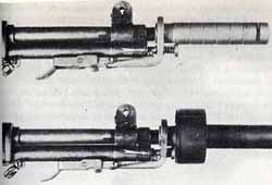
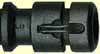
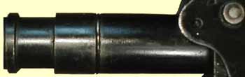
The existing M7A1 was given a "recoil hump" at the rear of the launch tube; this new design was the M7A2. Official publications state that the hump was designed to impact the newly developed "High Hump Lock" (Ordnance Part Number 7265871). The spreading of the launcher's impact acted as a rearward travel limit of the bottom mounted stud. This helped solved the potential problem of a broken valve head within the gas system. Shown at the right is a launcher in its most possible rearward position whose further movement is limited by the "High Hump" of the lock. The recoil hump and high hump lock were continued with the M7A3 production.
The Grenade Retaining Spring Change
There were two production versions of the M7A2. I refer to them as the Basic Design and the Improved Design. The difference was the accommodation of a new Grenade Retaining Spring. The field community was hoping that the R&D people finally solved the problem of lost retaining springs.
M7A2 Basic Design
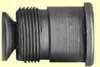
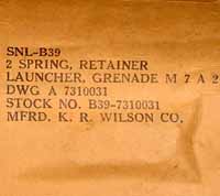
All GL's since the M7 were designed with a "Grenade Retaining Spring". This spring was located at the front of the launcher's tube and prevented a live projectile from slipping off. K. R. Wilson's first production run (Basic Design) had the 1940's type coil (also known as circular or helical) retaining spring, Ordnance Part Number 7310031, pictured at right. Shown also is one of the slots milled into the end which acted as a gas vent. This vent was used in early M7 production and some prototypes. Most Basic Design M7A2's were modified as shown below in the third illustration. Today very few Basic Design M7A2's exist.
M7A2 Improved Design
Under a contract modification, KRW produced the M7A2 (Improved Design) which used a wire form spring known as the "Hairpin Spring". The spring was assigned Ordnance Part Number 7266162. Based on years of observation I estimate the Improved Design to represent approximately 10% of the total M7A2 production. Installed during production and mounted in the same direction as the projectile's travel, the new spring was superior to the earlier coil spring. As the projectile's forward momentum was applied, the spring's mounted ends were locked in place by undercuts in the launch tube. With the adoption of the newer retaining spring, the cuts for the coil spring and the gas vents were eliminated. This spring and method of installation would be used in the entire production of the M7A3.
M7A2 Modified
During the life of the M7A2 mostly all of the Basic Designs were modified to use the later retaining spring. This modification might have been done after production. This type has been known as the "M7A2 Modified". The presence of cuts to accommodate both types of retaining springs is an easy way to identify the modification. Notice that the alteration utilized the top gas vent. This version probably represents approximately 95% of the M7A2 launchers that show up for sale. In the back of my mind I have to leave open the possibility that these launchers were produced this way. It is possible that during the transition to the newer spring it was decided to produce the launcher with provision for both.
The M7A2 also had a sight mount engineered into its body. This mount would allow the installation of a future sight. The sight would be calibrated for an improved anti-tank rifle grenade which was about to be used by US infantrymen.
Due to its design, shape, and size, I think the M7A2 is the most beautiful grenade launcher ever fielded.
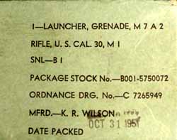
The M7A2 was packed in a light green box which was the signature of all of KRW's contract. This specimen is dated October 13, 1951. Photo was provided by Mike Popernack, an advanced collector who also has a website. Mike also has an excellent web page on grenade launcher development.
Mike's article was printed in the Garand Collectors Association's Journal a few years ago and stands out as one of my favorites. A visit to Mike's grenade launcher development page is well worth the trip.
The following two photographs were also provided by Mike Popernack. The right photo shows the two coil grenade retaining springs packed with the M7A2. The left photo shows the High Hump lock also provided by the contract.
The T87, Two Birds With One Stone
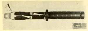
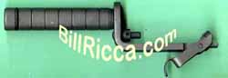
The T87, illustrated at right, attempted to upgrade the coil spring while looking for a solution for the semi-automatic problem.. A very heavy leaf spring was inserted in a longitudinal slot and staked in place. The grenade retaining end was bowed. The projectile compressed the bowed section, extending the spring down to the gas cylinder lock screw, opening the system. Arrow #1 shows the coil spring locking groove was filled in. Arrow #2 emphasizes the spring's shape. The top launcher shows the spring extending out of the launch tube to open the gas system. The spring did not hold up and the design was dropped. This design illustrates Springfield Armory's attempt to solve the coil spring problems as early as 1945. Eventually, in 1961, the M76 Grenade Launcher (M14) will be produced with a heavy leaf spring as the retainer.
Coil Springs Had A High Loss Rate, My Experiences
During the late 1960's through the mid 1980's, when prices were very low, I made it my interest to launch several hundred Inert Rifle Grenades, Amber Parachutes and Smoke Streamers where ever I had the chance. Catonsville, Maryland, The Howard County Dump in Maryland, Clark, N.J., South Jersey, and eventually Tampa Florida were all "Impact Areas" to carry out the fun. The launcher of choice was always the M7A1. I didn't like the M7 launcher due to its limitations. The M7A1 was readily available, and cheap. The M7A2's were too hard to find and very valuable. The M7A3's were also quite scarce and always in new condition; too nice to be used.
Several times (I estimate 5 or 6 times) I lost the coil spring while launching. Even brand new replacement springs would be gone after a few dozen launchings. I never foresaw any evidence of impending failure, just a missing spring after the projectile was gone. I speculate any of following reasons:
- The spring consists of a coiled wire which has its two ends connected by inter-locking curls. If either curl breaks, the spring will lose its circular shape and fly off the launcher.
- The spring consists of 81 coils and is limited to an outside diameter of .134 inches. With this limit, the wire used was only .016 diameter. It is possible that multiple launchings would wear through the wire at a given point around the circumference and the spring would fail.
- The speed of the projectile actually rolls the spring out of the locking groove in the launch tube.
I also experienced two broken valve heads when launching inert Energas with the M7A1. I was using gas cylinder lock #7265959.
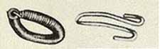
Coil Spring Ordnance Part Number 7310031 from 1943 shown at left. The coil spring was installed on both the M7 and M8 (M1 Carbine) Grenade Launchers.
Wire Form Spring (Hairpin Spring), Ordnance Part Number 7266162, similar to one tested during the late 1940's is shown at right. The hairpin spring was produced with a much heavier wire, .041 inches, more than twice the diameter of the coil spring's wire.
The T119 Grenade Launcher (3)
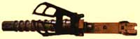
No study of the recoiling launchers is complete without mentioning the T119 Grenade Launcher produced by Mecar in Belgium. The T119 was for use with Mecar's Energa Anti-Tank Rifle Grenade (4). This 75mm projectile had a powerful punch and was capable of penetrating all but the heaviest Soviet armored vehicles. The T119 also had its own built in sighting system, in the form of a leaf sight. The sight was raised when in use and locked in the downward position for travel. In mid-late 1950 the US purchased the Energas and a small quantity of T119's from Mecar.
There is not much known about the actual use of the T119. I suspect it was thought to have too many problems. I also suspect it was never fielded, except for stateside training.
The T119's Two Shortcomings Severely Limit Its Use
The T119 was a poor design due to two features. The grenade retaining spring was located near the bottom of the launch tube. The "Bottoming" of projectiles was required with this design. Unlike other launchers that required bottoming to vent the operating gases, the T119 required bottoming to lock the projectile. The use of a bottom mounted retaining spring was dangerous. The mounting of a projectile any place but at the very bottom of the launch tube meant the risk of the grenade slipping off and detonating or being damaged. In the 1940's during the development of the M7, any launcher with a retainer mounted at the bottom of the launch tube was automatically rejected from further consideration. This was a safety consideration. I think this characteristic prevented the use of the T119 any place high explosive grenades would be fired.
Experience also showed that the grenadier's job must include the flexibility to launch different types of projectiles, different distances. The projectile's velocity and distance could not be easily varied. A bottom mounted projectile meant maximum velocity all the time. The T119 was fine for direct fire with its accompanying Energa grenade, but was poorly suited for other uses.
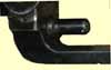
At right is a close up of the T119's Grenade Retainer. It had a very heavy duty spring of excellent design and quality, but unfortunately it was located just behind the first annular ring. A high explosive grenade mounted in front of this spring could slip off. Just to the right of the grenade retainer is the leaf sight rivet.
The T119 also had a second bad feature. It had a long stud similar to the WWII M7 launcher, making semi-automatic fire impossible. As long as the T119 remained on the rifle, the M1 was reduced to a repeater.
I think that Mecar may have been initially targeting other countries with its design, not the US. The company had to know of the existence of the M7A1 and possibly the M7A2 which was under developed during those times. Most likely the US either had to purchase the T119 to get the Energa as a complete system, for licensing to produce grenades, or as a stop gap measure until the M7A2 could be fielded. Whatever the case, it was poorly suited to do the job.
The T119 purchased by the US had the leaf sight calibrated in yards. Other countries also purchased it, without the T119 designation, calibrated in meters. Today the T119 shows up for sale on auction boards regularly. Like most items that were never adopted, the T119 is quite collectible.
It was soon discovered that the launchers in US inventory were not good choices for the Energa grenade. The launch tubes of the M7, M7A1, and M7A2 were too short to aim the grenades effectively. With the Energa mounted, the rifle was unbalanced and front heavy. The remedy was to extend the launch tube which gave the projectile greater velocity, stability, and accuracy. The M7A3 was the answer.
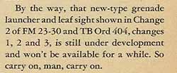
I believe the two deficiencies of the T119 kept it from being adopted. At right is an article from the September of 1955 issue of PS Magazine. Almost five years after initial purchase the T119 was still considered "under development". I think by then a contract was already signed to produce the M7A3 launcher with its own leaf sight. Shortly after the publication of this article, the leaf sights for the M7A3 would first appear. I estimate the first fielding of the leaf sight to be circa early-mid 1956.
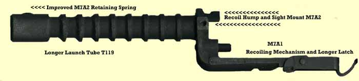
The M7A3 Grenade Launcher 


After 10 years of experience with the earlier designs, the engineers came up with a launcher that would need no changes, nor improvements. It had the M7A1's recoil mechanism. It had the M7A2's recoil limit, improved grenade retainer, and its ability to mount the leaf sight that was in the near future. Its longer launch tube was influenced by the T119. The new length allowed the grenade cartridge's propelling charge a longer burn time, resulting in an increased velocity for the projectile. The M7A3 was all business. It was a proven winner. PHOTO It was officially standardized in September of 1952.
-
 R. Wilson of Arcade, New York, (KRW) was the first contractor of the M7A3. Shortly after completion of the M7A2 Grenade Launcher contract, KRW was awarded a contract to produce the first M7A3. Having been in production of the M7A2, KRW had a fast initial delivery. This box is dated Jan. 1953, only three months after standardization. Packed with the launcher was the high hump lock. K. R. Wilson also had a contract for M3A1 combination tools during the same period.
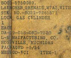
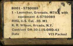
This launcher is often identified as being produced by Long Manufacturing; it is obviously wrong. L-M Manufacturing (L-M) of Roseville, Michigan was the producer. The L-M launcher was also packed with a high hump lock. Package date is May 1954. The photo to the right is a joint image of a wrap around label. I have always considered KR Wilson, Sun Ray, and L-M the early producers.
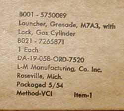
The removal of the outside wrapper of the L-M Manufactured M7A3 exposes a beautiful cardboard sealed box, with the shown contract and nomenclature information. The information is easier to read, but just a duplication of the outside wrapper.
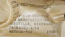
On the right is the high hump locked packed with the L-M Manufacturing M7A3. The lock was packed in April of 1954 and was inside an M7A3 packed in May of 1954. Obviously the dates of manufacture can vary by a few months.
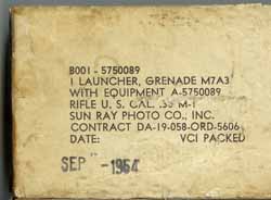
Shortly after K. R. Wilson's contract, Sun Ray Photo Company (S.R.) got a contract. Packing date is Sept. 1954. This launcher was packed with a high hump lock. I have production broken into two categories of time. This contactor is another early producer. The contract may have had either a delayed start, a spread out delivery period, or took a long time to get into production. Notice the contract number from the same agency is earlier than that of L-M Machine's contract shown above, but with a later packing date than L-M's production.
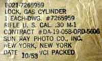
High Hump Lock packed inside a different Sun Ray Photo Grenade Launcher package. Same contract as the launcher shown above but an earlier date. Notice the drawing number indicates the flat edge lock. I suspect Sun Ray's contract may have initially specified the flat edge, then was changed to the high hump lock. This wrapper probably remained on hand and eventually was used to pack the high hump lock. More research is going on here, more to come.
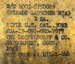
The M7A3 produced by The Dockendorff & Company (DOK) seems to be the scarcest of all. From the label markings the gas lock was not part of the contract; however, that may not be the case. At the end of this section I have presented an analysis of the part numbers.
Package date is October of 1955. What I refer to as the later category of production included two New England companies, Dockendorff and Acme Machine. These two contracts were late enough to require the Defense Acceptance Stamp marking on the launchers..
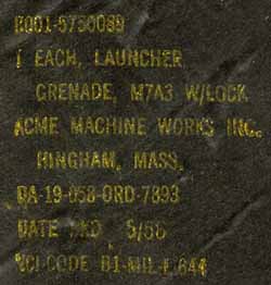
Acme Machine Works of Hingham, Mass., (ACME) was the last producer of the M7A3. This was the only launcher contract that specified the black asphaltic cardboard tube. Heavy cardboard is twisted and turned around an asphalt barrier. The ends were sealed with circular metal closures. By the mid 1950's many Springfield Armory contracts specified this form of vapor barrier protection. The asphalt prevented moisture from getting to the Volatile Corrosion Inhibitor Paper that surrounded the launcher packed inside. Due to the added weight of the M7A3, the high hump lock was no longer considered a must use item. This launcher was packed in May of 1956.
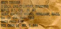
Flat Edge Lock as manufactured and packed inside the Acme Machine Works packing tube. Note the packing date of April 1956. This lock was packed inside an M7A3 delivered in May of 1956.
The above original packages present a mystery. The M7A3 was assigned Ordnance Part Number 7266167. The ordnance part number 5750089 is the part number for a launcher packed with a gas lock. The DOK launcher's package does not mention the gas lock, but reflects the part number for the pair. I don't want to open the sealed package to find out. Notice some of the packages are marked B001 (B-1). This B-1 designation is the Standard Nomenclature Listing for "Major Items in Group B", which applies to many small arms items. During WWII Grenade Launchers had their own separate SNL assignment of B-39.
By 1962 the heavier HEAT projectiles were to be launched only from the M7A3. The M7A1 was pretty much gone from combat units. The M7A2 was restricted for use with Ground Signals only. Technical documents state that either the high hump lock or flat edge lock were acceptable for use with the M7A2 and M7A3, but one must analyze the restrictions in place.
The breaking of valve heads was the result of launching the heavier HEAT and M29 Practice projectiles from the M7A2 using the flat edge lock. The M7A2 had no history of getting stuck and would not result in broken valve heads with the lighter ground signals. The high hump lock was the preferred lock, but the flat edge lock was acceptable with these restrictions in place. The M7A3, with its added weight and recoil hump, could be used with either lock. The M7A3 had fewer potential problems. To sum it up, it was probably easier to accept a small number of broken valve heads with the limited number of M7A2's left in training areas, thus either lock could be used on any of the launchers.
The M7A3 Gets Its Own Sight
In the publication The M1 Garand: Post World War II, Scott Duff (5) mentions a company named Cooperative Machine Company. Scott has found Springfield Armory records that awarded Cooperative Machine a contract for 63,000 M7A3 GL's. The award period is from Jul 1954 through December 1954. Scott's records also show the Dockendorff contract was awarded during the period of Jan 1954 through June 1954. Dockendoff's delivery is over a year later.
As of yet, nobody has seen an M7A3 that can be attributed to Cooperative. I am going to offer a possibility. Suppose Cooperative's contract initially called for the M7A3 to be produced with the new leaf sight. Suppose it was decided that, with the M14 breathing down everybody's neck, there were enough launchers in the system. What if the contract was changed to eliminate the launcher and provide just a limited quantity of sights? Cooperative's delivery period would fall in line with the first appearance of the M7A3's leaf sights. The circumstances just seem to imply it.
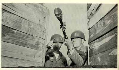
This is a K. R. Wilson M7A3 with the US designed and manufactured leaf sight. These sights, which existed in small quantities, were added to existing launchers at the Direct Support Level. The sights were calibrated for the Energa grenade. Now the grenadier would have the advantage of the integral sight for direct fire, the flexibility to use his launcher in other roles, and still use the M1 in its intended semi-automatic role. As 1960 approached, the army was working on a more aerodynamic rifle grenade with a piezoelectic crystal for a detonator. This made the Energas and the leaf sights on the M7A3's obsolete. Evidence shows the sights were removed and scrapped. The leaf sights probably were used for approximately 3 years. Interviews of individuals serving during 1959-60 show they were gone by then. Today it is very hard to find a reference to their actual use. At the right is a Basic Training photo taken at Ft. Jackson, South Carolina in 1957. The photo shows both the sight and the training version of the Energa, captured in history forever.
A Visual Comparison (Not Quite to Scale)
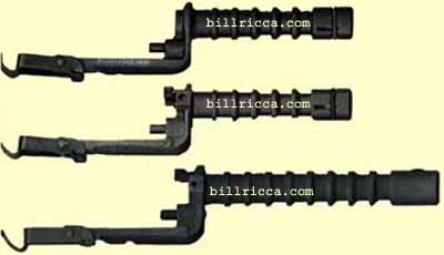
Top: Rock Island Arsenal's M7A1 GL, Part. No. 7313286-3. Gas ports, which were three longitudinal slots 120 degrees apart, were included in the M7A1. The launch tube began thick at the first three annular rings which were next to the launcher's body (bracket), then reduced down.
Middle: M7A2 Basic Design, Part No. 7265949, produced by K. R. Wilson. The Basic Design was an exact duplication of the M7A1, but with the addition of the recoil limit.
Bottom: M7A3, Part. No.7266167, produced by Sun Ray. The M7A3 was a exact duplicate of the M7A2 Improved Design (see spring change in M7A2 section), but longer. The longer launch tube maintained the thicker dimension for its entire length.
All launching formation on this page is for historical and interest purposes only. I do not recommend that anybody attempt to duplicate what I have done. Launching any projectile can result in serious injury or even death. Anybody asking for advice on the launching of any projectile will be advised not to do it.
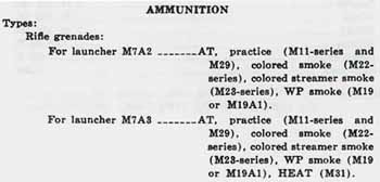
Projectiles
On the right is the European version of the Energa. Not visible is Mecar's Armaments and Munitions trademark. Unlike the Energas from US inventory which had rocket fins, the European version had a circular stabilizer. This particular practice projectile is dated 1962. While trying to sell its Model 01 version of the M16 to foreign countries, Colt's 1964 sales catalog advertised the rifle's compatibility with the Energa grenade. This projectile may have been a salesman's sample.
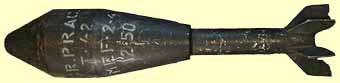
US T42, Inert Projectile from Dec of 1950 (marked T-42). This was probably part of the first US purchase in 1950. Possibly produced in the US, under license from Mecar. It is still unknown whether MEF is an old abbreviation for Mecar, or a stateside contractor.
A beautiful blue version from Feb of 1952(6). I want to thank Ed Strazdes for this picture. Ed has many US and foreign projectiles listed on his website, inert-ord.net. Just click on Ed's name anywhere on this page for a direct route to his site.
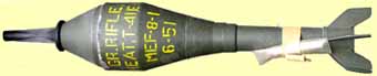
Thanks to Rick Larson for this beautiful example of a T41E1, complete with fuse protector. This grenade became the M28. Notice the M3 Grenade Cartridge taped to the launch tube. If you visit the Oregon Military Museum in Clackamas, Oregon, make sure you say hello to Rick.
Rick also sent this image of a HEAT cutaway which is on display at the museum. It shows how the explosives are contained to produce the shape charge which penetrates the armor.
Inert Warheads
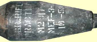
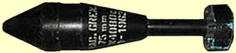
By October of 1953 the T42 was already designated as the M29. All practice projectiles I have for sale are from the early 1950's and have MEF as the lot. This one has had its share of launchings, as is visible by the rust and missing paint on the wind screen (nose). The markings are M29 (T42). This is from a large lot, most of which still remains in my possession. The lot was released at Pueblo Army Depot in the mid 1960's.
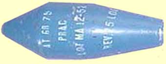
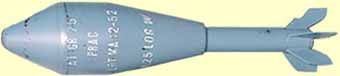
Here is a practice projectile from December of 1952. It seems the doctrine of blue equals inert took a while to implement as many inert were delivered with a black finish. The designation AT GR 75MM and the MA lot marking make me believe that this one definitely was produced by Mecar.
My Partner in Fun
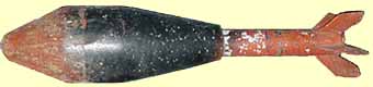
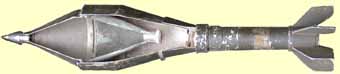
Shown here is the US GI T42 (M29 Practice) Inert Rifle Grenade, as altered for launching. Old Red is an experienced veteran and has survived several dozen launchings. The wind screen and tail are painted red. The red tail makes visibility in grassy pastures very easy. The black area is necessary to track its flight through the air. It is missing one tail fin, has one bent fin, and still flies pretty true. A reason for its survival is that most of its launchings were straight up. I have found that launching for distance (angles less than approx 65 degrees) can cause the projectile to ricochet off the warhead section, causing the tail fins to impact the ground, damaging them. This projectile even survived a few dozen launchings from 300 Weatherby Magnum Grenade Cartridges I developed during the late 1980's. The rifle was a re-chambered British P14 with a specially altered M7 Grenade Launcher. This partner in fun has been used predominately here in Pennsylvania on my property. A well used M7A3 was the device of choice since moving here in 1986. One look at the Energa's bulk and it is no wonder that past launchings from the M7A1 have destroyed two lock screws.
Mecar, Today
By the 1970's Mecar had started marketing "Bullet Trap" Grenade Launching Systems. One of the shortfalls throughout the years was the requirement for special Grenade Cartridges. In the bullet trap system the projectile has a specially designed steel trap inside the launch tube. The bullet from standard service ammunition impacts the trap. The bullet is stopped inside the tube and the resulting energy is transferred to the projectile for launching. Mecar has produced the system in both 7.62mm and 5.56mm. The company lives on, marketing defensive armament systems to the world.
(1) My thanks to Tom Tangen for providing Rock Island's production information on the M7A1. Tom got in touch with the facility and received the actual production numbers. This report uses an approximate number. When researching ordnance production it is important to remember that reports are usually based on fiscal years, not calendar years. This is for funding accountability. Tom's report covers 1 July 1948 thru 30 June 1949.
A former Rock Island employee remembered hearing that the facility had produced GL's twice. Which launchers and when, he did not know. This may explain the two different part numbers for the M7A1. Finding the ordnance drawing will finally clear it up. The M7A1 is pictured in TM 9-1275 from 1947. That date is before the production date recorded at Rock Island. It appears to be one of the competing designs, without the gas vents.
(2) I thank Rex Gallogly for his M7A2 production figures and dates. Rex is working on a book covering Grenades, Rifle Grenades, and Launchers. Rex's book will go into much more detail than is shown here. I will announced the availability when the book is completed.
(3) I want to thank Rick Larson for sharing his copy of Technical Bulletin (TB) ORD 404 from December of 1951. The TB goes into the details of use and stocking of the T119 Launchers and the Energa Grenades. Rick's knowledge on GL's is quite vast, and extends to present day systems.
(4) There were two types of Energa grenades purchased for US forces, an inert training model (practice) and a high explosive anti-tank version (HEAT). Each had a different "M" designation. For the purpose of this history I have chosen to use the term "Energa" which includes both models. It is easier and will cause less confusion.
(5) Many thanks to Scott Duff for uncovering the buried information on Cooperative Machinery. Click on Scott's name anywhere in this history for a direct route to his website. Scott's knowledge in US Small Arms needs no introduction.
(6) Thanks to Ed Strazdes at inert-ord.net for this perfect picture. Ed has a detailed page for US Rifle Grenades.
Click Here to read about the last generation of US Grenade Launchers.
This information may be used freely for message boards discussions. Permission must be granted for use on websites, for publication, or for inter-net auctions. Don't be afraid to ask, you may be surprised.